Notations and Conventions
This document provides an overview of the notations and conventions being used within eSSIF-Lab.
RFC 2119
We use keywords such as “shall”, “should”, “may” etc. as defined by RFC 2119.
Capitalization of words in mid-sentence
A word in mid-sentence that is capitalized is a term that has a definition in the Corpus of Terminology. This allows readers to distinguish between the more colloquial meanings of words (by not capitalizing them) and those that are actually defined. We appreciate any feedback regarding our (im)proper use of this kind of capitalization of words.
We are working towards deprecating this convention, as we now have better ways of referring to words that are defined in the eSSIF-Lab Corpus.
Pattern diagram notations
Pattern diagrams will be visualized in this document using a notation that is very similar to that used by UML. The following diagram shows the various notations that we will be using that are basically taken from UML. There are a few exceptions, that are not shown in the figure; they are explained at the end.
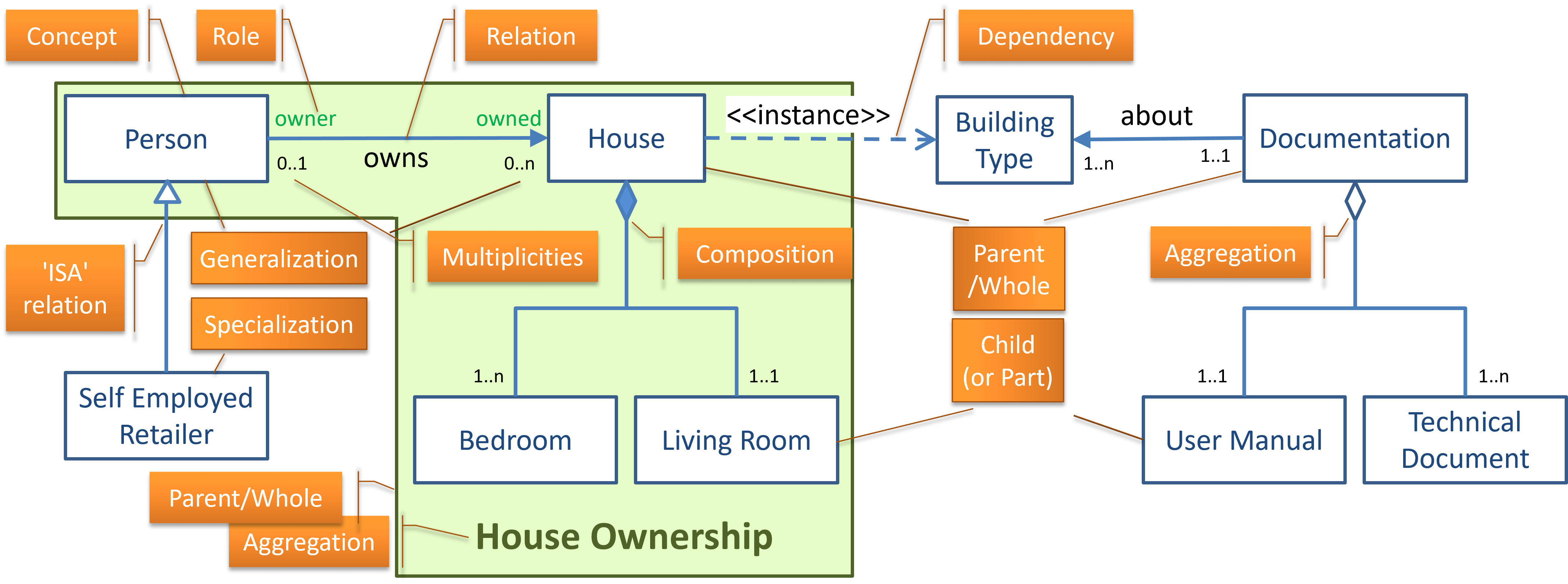
A rectangle, e.g. 'Person', represents a (named) concept, or entity-class. The (operational) extension of a concept is the sets of its instances (for 'Person', the extension consists of the set of actual people of flesh and blood tha are in the scope of the model). The extensions of different concepts are disjunct (do not overlap), unless there is an 'ISA' relation between them (see below). When a rectangle is in a coloured area that has a name, it is a child (or part) of the concept with that name (see below)
A solid line with a closed arrowhead, e.g. 'owns', represents a (named) relation/association between the two concepts it connects. The concept at the arrowhead ('House') is called the 'target concept' (TGT) for that relation; the other ('Person') is called the 'source concept' (SRC). The relation is labeled such that <SRC> <relation label> <TGT> (Person owns House) suggests the phrase that describes the intension(al definition) of that relation. The (operational) extension of a relation embraces all pairs (SRC,TGT) for which the relation holds. In the example, it consists of all pairs (P,H), where P is a Person and H is a House, such that the phrase 'P owns H' is true.
A green name at either end of a relation/association is what UML calls 'role'; this name may be used to refer to (an instance of) the concept at which the name is placed as it performs its/this role in this relation. In the figure, owner is the role that a Person fulfills in the relation 'owns'. If we assert that a Person (P) is the owner of a specific House (H), or that House H is owned by Person P, this means that (P,H) is an element of the extension of the relation 'owns'.
A solid line with an open arrowhead, represents a generalization relation. It can be read as <SRC> is a <TGT>, and is therefore also referred to as an ISA-relation. The SRC of the relation is the specialization (subclass) of the TGT (which in turn is a generalization of SRC). This means that SRC satisfies all constraints that TGT satisfies, and also that SRC has all attributes (properties, characteristics) that TGT has. The figure shows 'Self Employed Retailer is a Person' as an example.
A line with a solid diamond at one end represents a composition relation. The element at the 'diamond-end' is called the 'parent', or the 'whole'. The other element is called the 'child' or the 'part'. A 'part' in a composition relation cannot be part of more than one 'whole'. Normally, if a 'whole' in a composition relation ceases to exist, then so do all of its composite parts. In the figure, at least one Bedroom and precisely one Living Room are parts of a (every) House. Obviously, if a House ceases to exist, then so do these rooms.
A line with a hollow diamond at one end represents an aggregation relation. The element at the 'diamond-end' is called the 'parent', or the 'whole'. The other element is called the 'child' or the 'part'. A 'part' can be a part in multiple aggregation relations, and hence be part of multiple 'wholes'. If a 'whole' in an aggregation relation ceases to exist, the parts typically continue their existence. In the figure, 'Documentation' (about a Building Type) is an aggregation of a 'User Manual' and at least one 'Technical Document'. Obviously, if the Documentation ceases to exist, then the 'User Manual' and 'Technical Documents' typically continue to exist.
-
A dashed line with a pointed arrow (
>) represents a dependency, where the SRC concept somehow depends on the TGT concept. The kind of dependency is specified by a<<text>>. In the figure, we see a dependency relation relation<<instance>>, indicating that 'House' is a specific instance of 'Building Type'. -
A [n..m] structure represents a multiplicity. When it appears
- at the TGT end of a relation, it means that for every SRC element there must be at least n and at most m TGT elements in the relation. For example, the [0..n] multiplicity in the 'owns' relation in the figure means that for every 'Person' element, there must be at least 0 and at most n (i.e. any number) 'House' elements. Effectively, this says that every Person can own any number of Houses.
- at the SRC end of a relation, it means that for every TGT element there must be at least n and at most m SRC elements in the relation. For example, the [0..1] multiplicity in the 'owns' relation in the figure means that for every 'House' element, there must be at least 0 and at most 1 'Person' elements. Effectively, this means that every House can be owned by at most 1 Person.
- is typically of any of the following forms (although there may be others, e.g. [1..2]): [0..1]: at most one; [1..1]: precisely one; [0..n]: any number - as this is not a constraint, this is the default multiplicity and may be omitted; [1..n]: at least one. Note that the term multiplicity is distinct from cardinality, the difference being that a cardinality states the actual number of SRC/TGT elements that a specific TGT/SRC element has in a relation, whereas a multiplicity states the possible number of such elements. In short, the multiplicity is the set of all possible cardinalities in a relation. We note this becaus it is common practice for people to use the term 'cardinality' where 'multiplicity' is intended.
-
a named and coloured area, e.g. the green area named
House Ownershipis the aggregate (Parent/Whole) of all concepts (rectangular elements) therein, which are its children/parts. This aggregate can be linked/associated with any other concept, including its children/parts.
Notational Exceptions
The following notational conventions are not used by UML, but are specific to our use.
We use a coloring convention to distinguish between what is 'officially' part of the eSSIF-Lab models, and parts that are not.
- blue is used to color the lines and other symbols that are part of the 'official' models. Typically, they are explicitly defined or otherwise explained, e.g. in a mental model. Their definitions/meanings may differ from 'common knowledge'.
- red is used to color the lines and other symbols that are part of our 'common knowledge', and hence need not be explicitly defined. They appear to explain where eSSIF-Lab models link to these commonly known/used concepts. We think of them as necessary in order to bridge possible gaps between 'common understanding' and the eSSIF-Lab ways of thinking. Whenever a 'red concept' is nevertheless defined, this is for the purpose of conveying what we conceive the 'common knowledge' to be.
We use a line typing convention within a diagram, as follows:
- solid lines are used for lines and other symbols that are part of the model that is represented by the diagram;
- dashed lines are used for lines and other symbols that are (authoritatively) defined elsewhere. For example, the concept party is authoritatively defined in the party, actor and action pattern, so the diagram there shows a solid (blue) line for that concept. It also appears in other diagrams, e.g. in the jurisdiction pattern, where the concept is represented with a (blue) dashed line.